Week 11: Input Devices

Input Devices
Input devices are hardware components used to provide data and control signals to an information processing system, such as a computer or microcontroller. Our world is filled with these devices. We encounter them daily—when we open the refrigerator door and the light turns on, or when we take our temperature and a red light illuminates, for example.
To correctly understand and utilize input devices, it's important to consider several aspects. When reading a digital input (HIGH or LOW), we use the digitalRead function. HIGH always indicates that voltage is present on the pin, which depends on the power source (5V, 3.3V, etc.). To prevent floating states, we must use a pull-up resistor or debounce the signal.
Pull-up Resistor: Its primary role is to pull the input to a safe, high logical state (HIGH) when the switch is open and no other input signal is present. This prevents the input from "floating" and adopting undefined states, which could be caused by electrical disturbances. When the switch is closed, the input is short-circuited to ground (GND), resulting in a low logical state (LOW).
Debounce: Stabilizing the signal can be achieved through software, where the input from the switch is checked after a small delay, or through hardware, using circuits like capacitors and resistors.
For reading analog inputs, we use analogRead. Voltage dividers are crucial for reading analog signals to protect against damage from excessively high voltage.
Level Shifter: Various devices operate at different voltages. To allow these devices to work together, voltage levels must be aligned, which is achieved using a level shifter.
Three key tips for using sensors are:
- The Simpler, the better
- Look for existing solutions first, such as those found on learn.sparkfun.com, learn.adafruit.com, or GitHub.com
- Utilize libraries, especially for digital sensors, to streamline software integration
List of Sensors
- Switch Sensors - Switch sensors often use a pullup resistor to ensure the current isn't floating
- Magnetic Switches - These switches detect the presence or absence of a magnetic field
- Potentiometer - Functions like a voltage divider
- Light Sensors - Could be a phototransistor that allows more or less current to pass based on the light intensity. An LED can also be used as a light sensor
- Motion Sensors - Detect movement within a given area, often used in security systems and automation
- Distance Sensors - Use two pins to measure the time it takes for a signal to travel to an object and back, effective up to 2 meters, and not suitable for very close distances. More recently, this technology can also be implemented using lasers, although light conditions can affect accuracy
- Location, Time Sensors - Used to determine geographical position and timing, essential for navigation and time-sensitive applications
- Acceleration, Orientation, Rotation Sensors - Measure acceleration, the orientation of an object in space, and rotational movements, commonly used in mobile devices and gaming controllers
- Sound Sensors - Various microphones that capture audio for processing and analysis
- Piezo Sensors - Contains a piezo element that can also function as a sensor, capturing vibrations or impacts, such as a tap on a table
- Pressure Sensors - These are resistors that change resistance with applied pressure, used in touch-sensitive applications and monitoring environments
Soundboard
Since I wanted to work with sound in my final project, I wanted to produce a PCB that outputs sound this week. I initially searched at Adafruit, but then my tutor recommended the this piano to me.
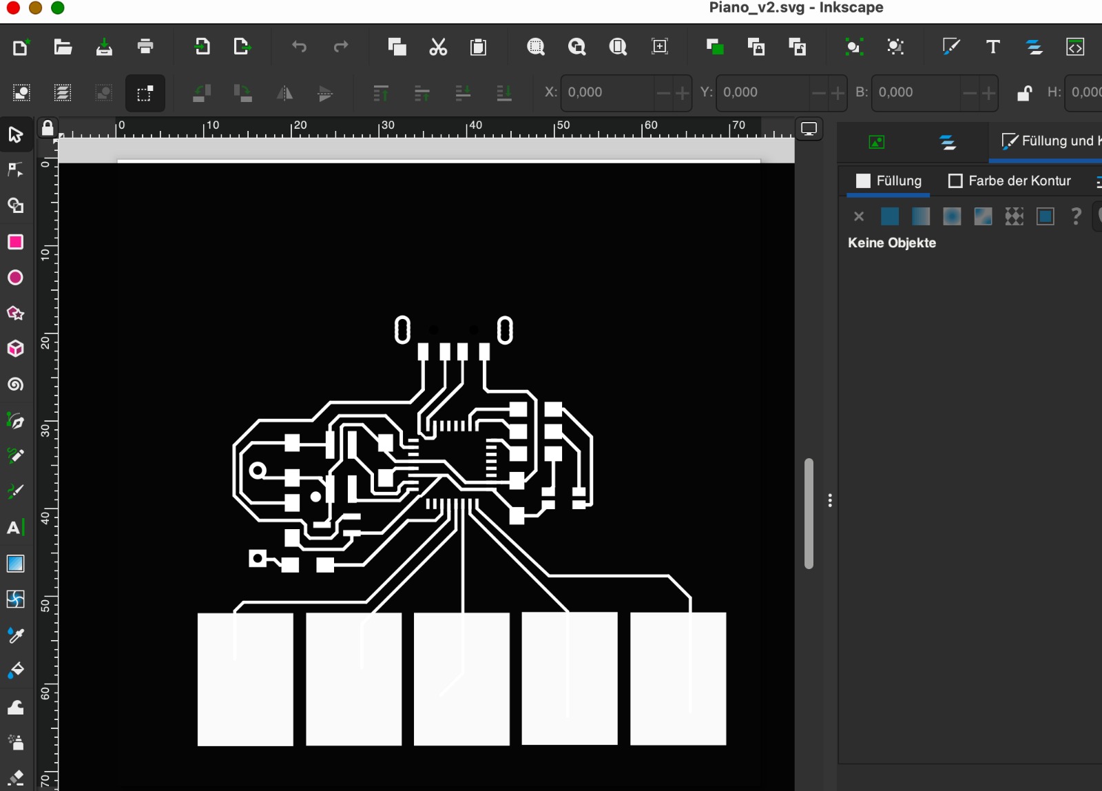
I downloaded the files and initially adjusted them. I changed the footprints and selected a different USB port. I initially left the footprints round in KiCad, but shifted them a bit. My plan was then to adjust the shape in KiCad so that the areas were a bit larger and square.
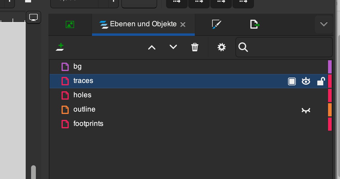
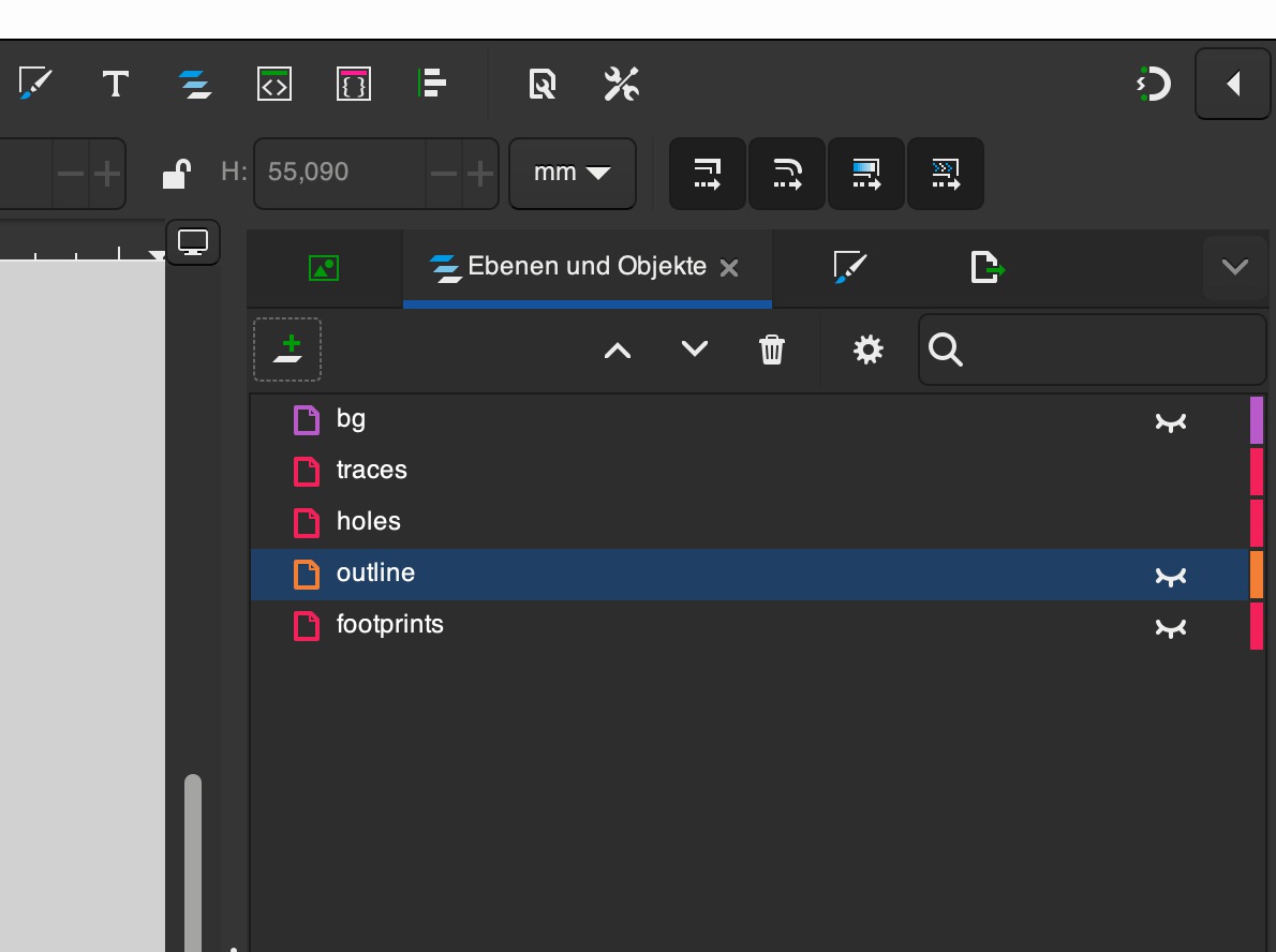
Now I can easily adjust the colors of all traces, footprints, holes, and the outline. For the export, I only make visible the parts that I want to see on my PNG. First, I select traces and footprints, then holes, and then outline.
Now I have four PNGs, which I upload one after the other on the following page https://modsproject.org/ and prepare for cutting. I follow this path: Right click/open programs/open program/Roland/SRM 20 mill/mill 2D PCB, to open the correct page. I then enter the settings that I already used and described in week 4.
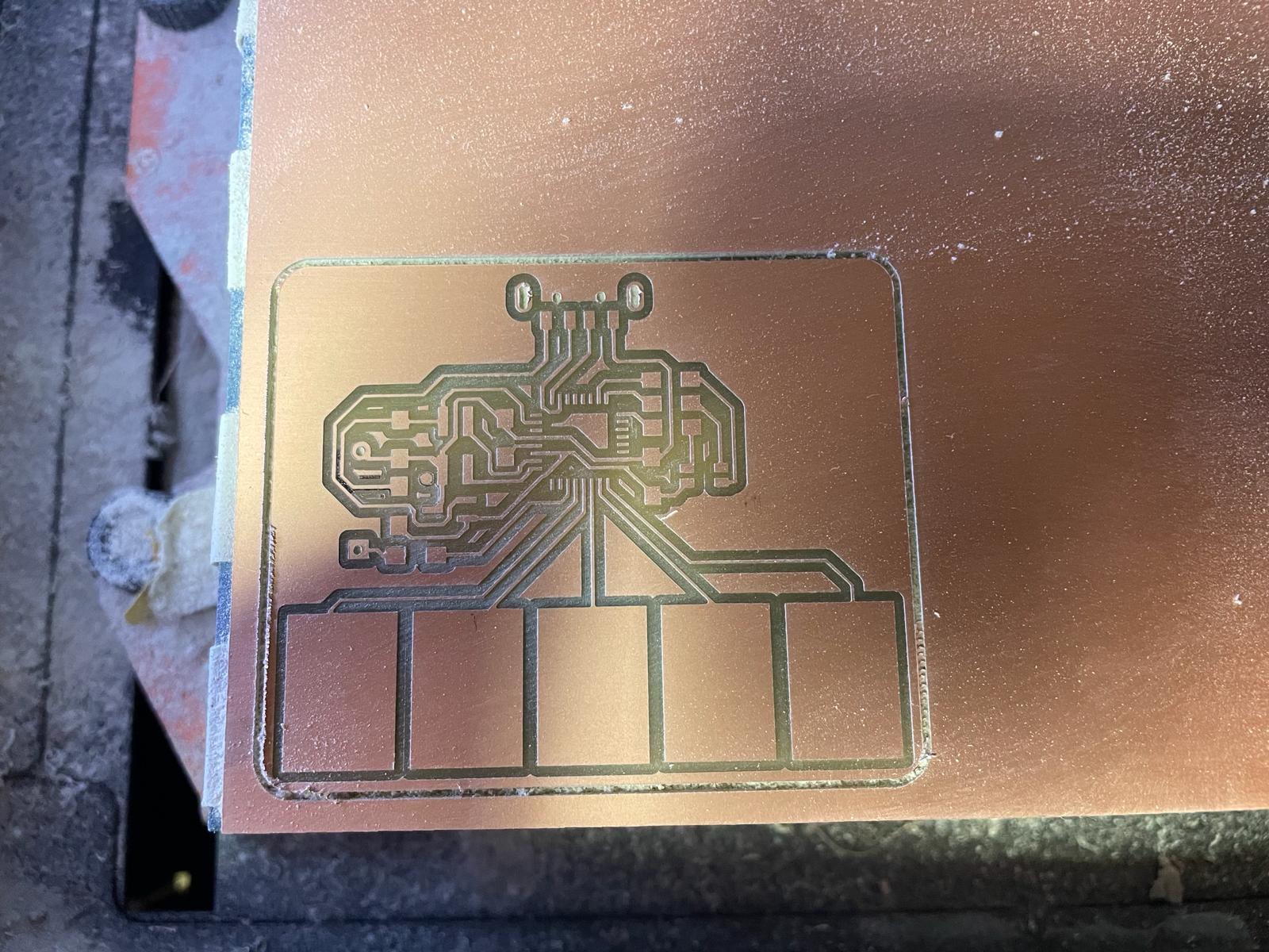
Then I go to the machine and mill the PCB. Unfortunately, the result after the first cut of the traces is not satisfactory, so I have to repeat a cut on the same PCB after setting the z zero a bit lower. After that, the result is good and I create holes and outline. Now I start soldering. Unfortunately, my tutor then notices that I chose the wrong footprint for the USB port and that we do not have a USB port that fits my footprint in the lab. I had to produce the board again.
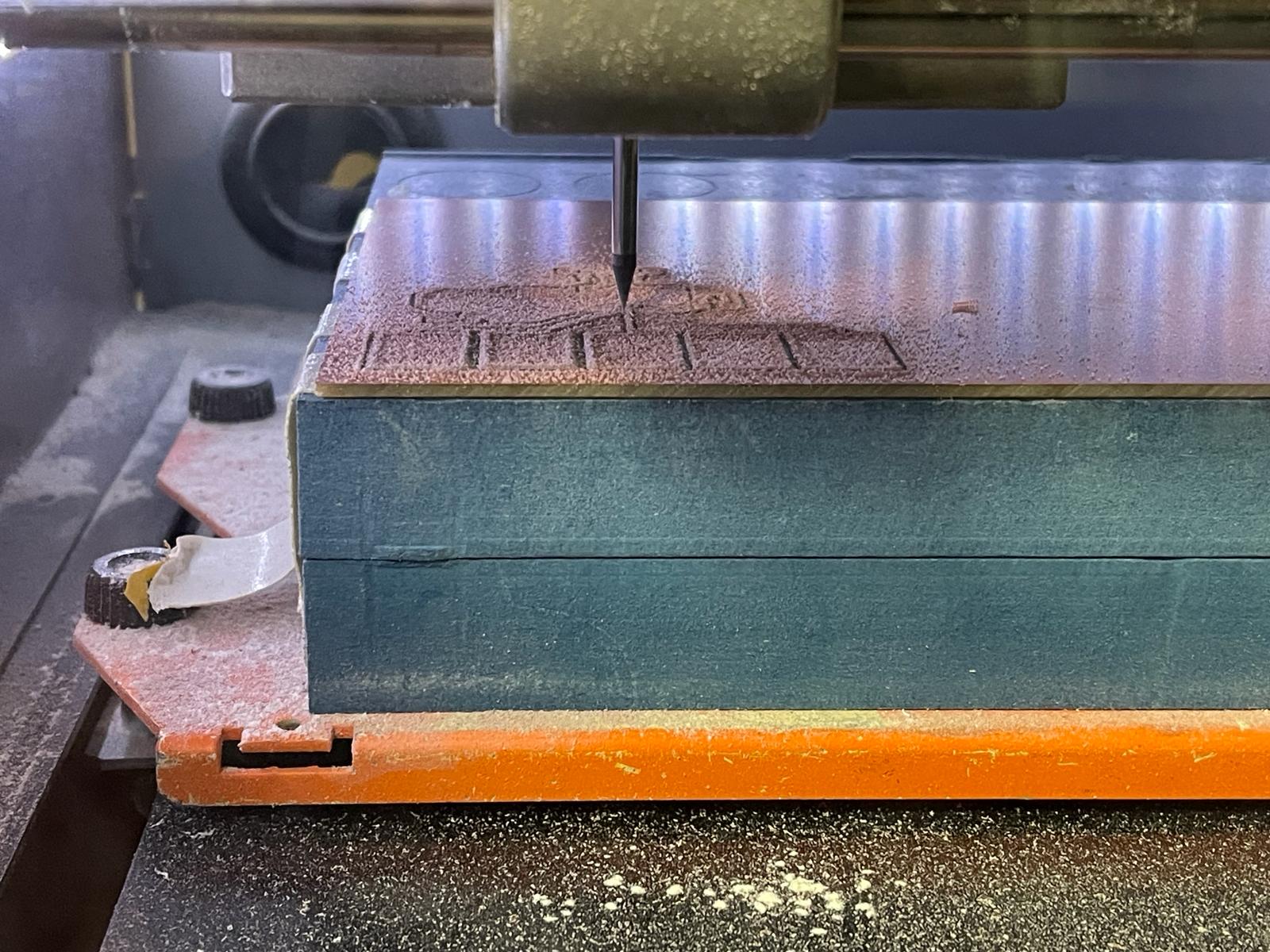
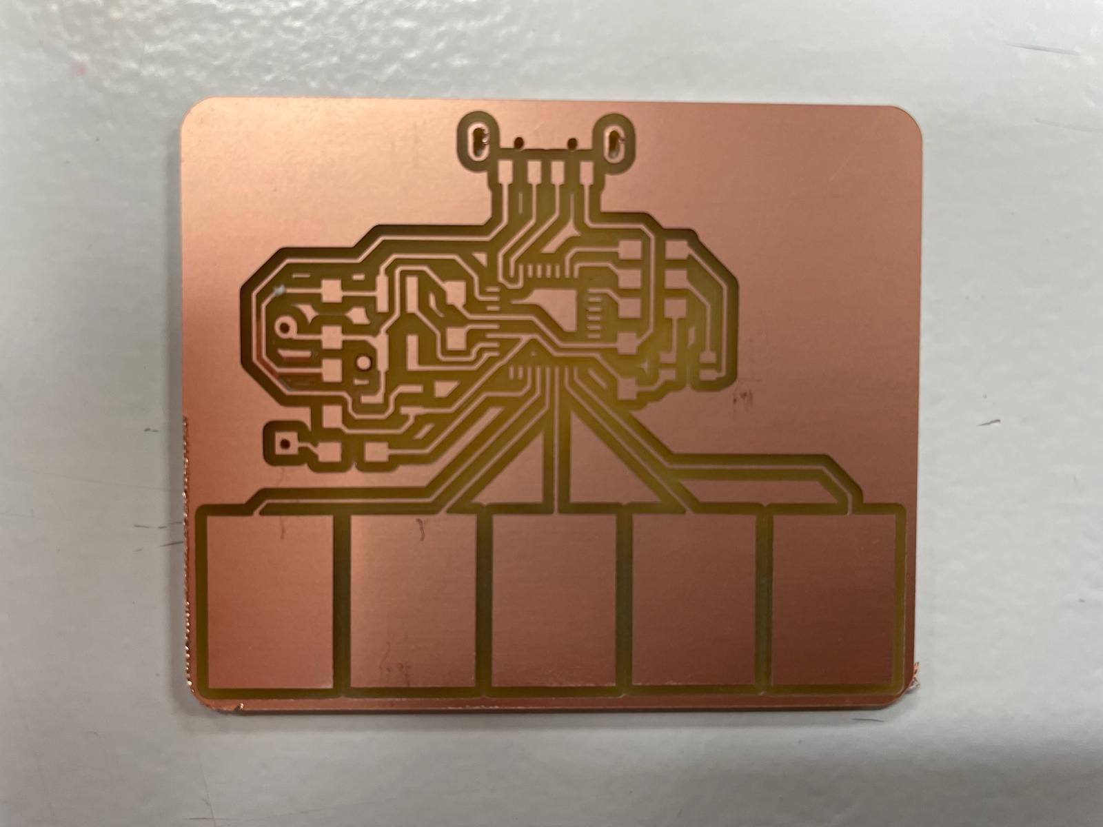
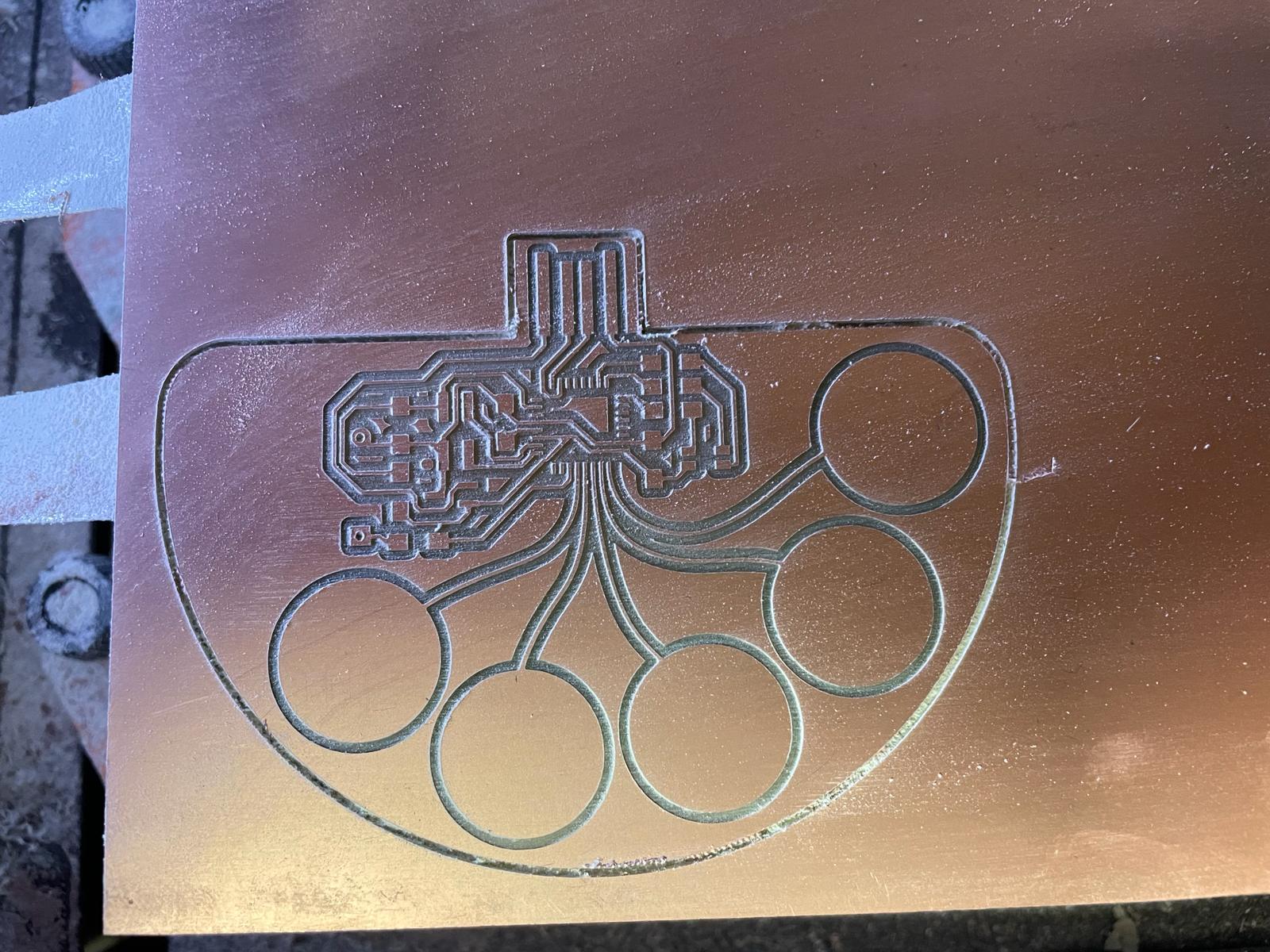
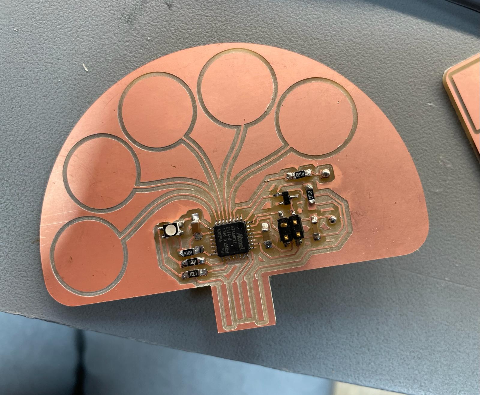
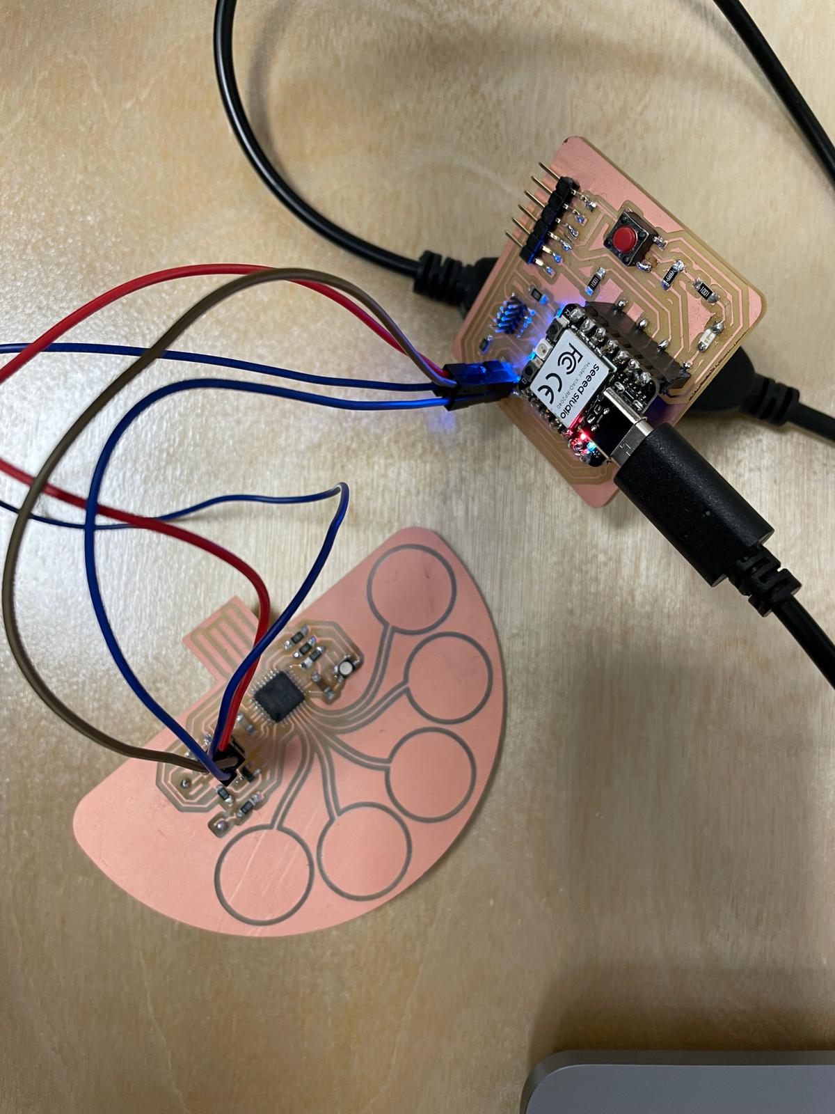
Due to lack of time, I then decide to use a different already finished version from the side above. I prepare it for the CNC machine. The cut goes well and I can solder all the elements.
Programming
 When I am done, I use my Quentorres as a bootloader and follow the steps that were already described in week 8.
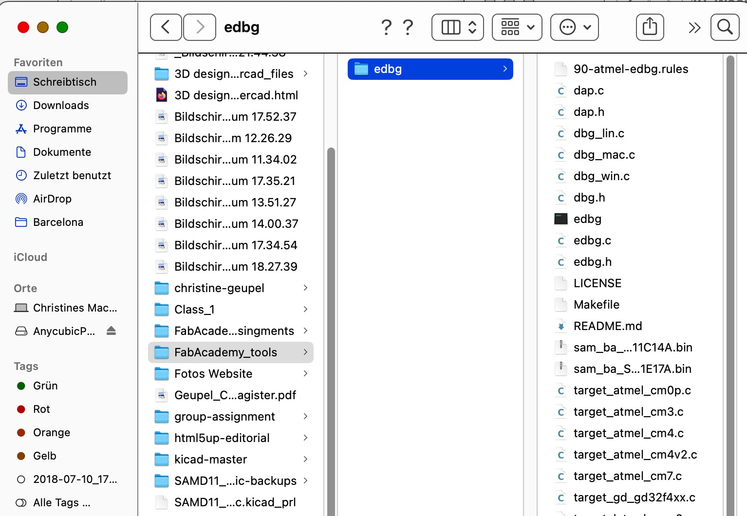 Unfortunately, this did not work and my tutor and I then tried a different way. On the desktop, we had already placed a folder with FabLab tools last time, which included an edgb file. It already contains many files, including a SAM11 file. Under this link, I was able to add the file for the SAMD21 by downloading this file and placing it in the folder.
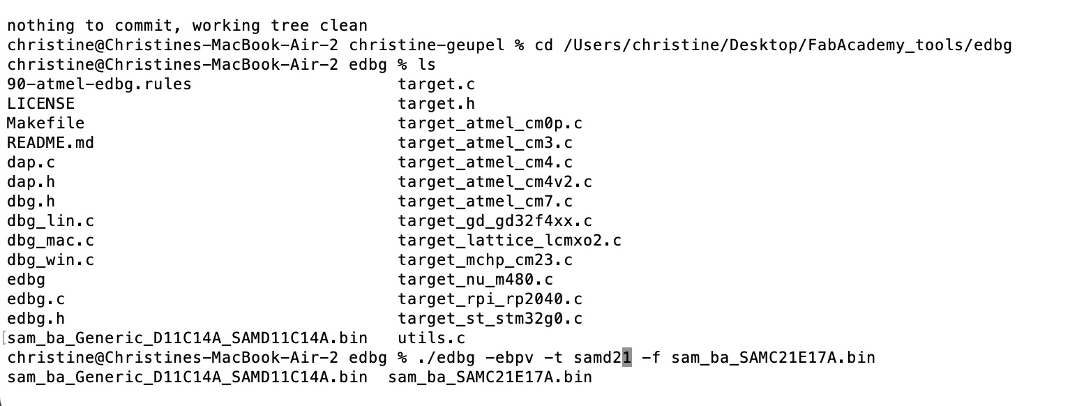
Then we navigated to the terminal. There we entered the following commands:.
cd /Users/christine/Desktop/FabAcademy_tools/edbg (to go to the appropriate folder)
ls (to see if the file is in the directory)
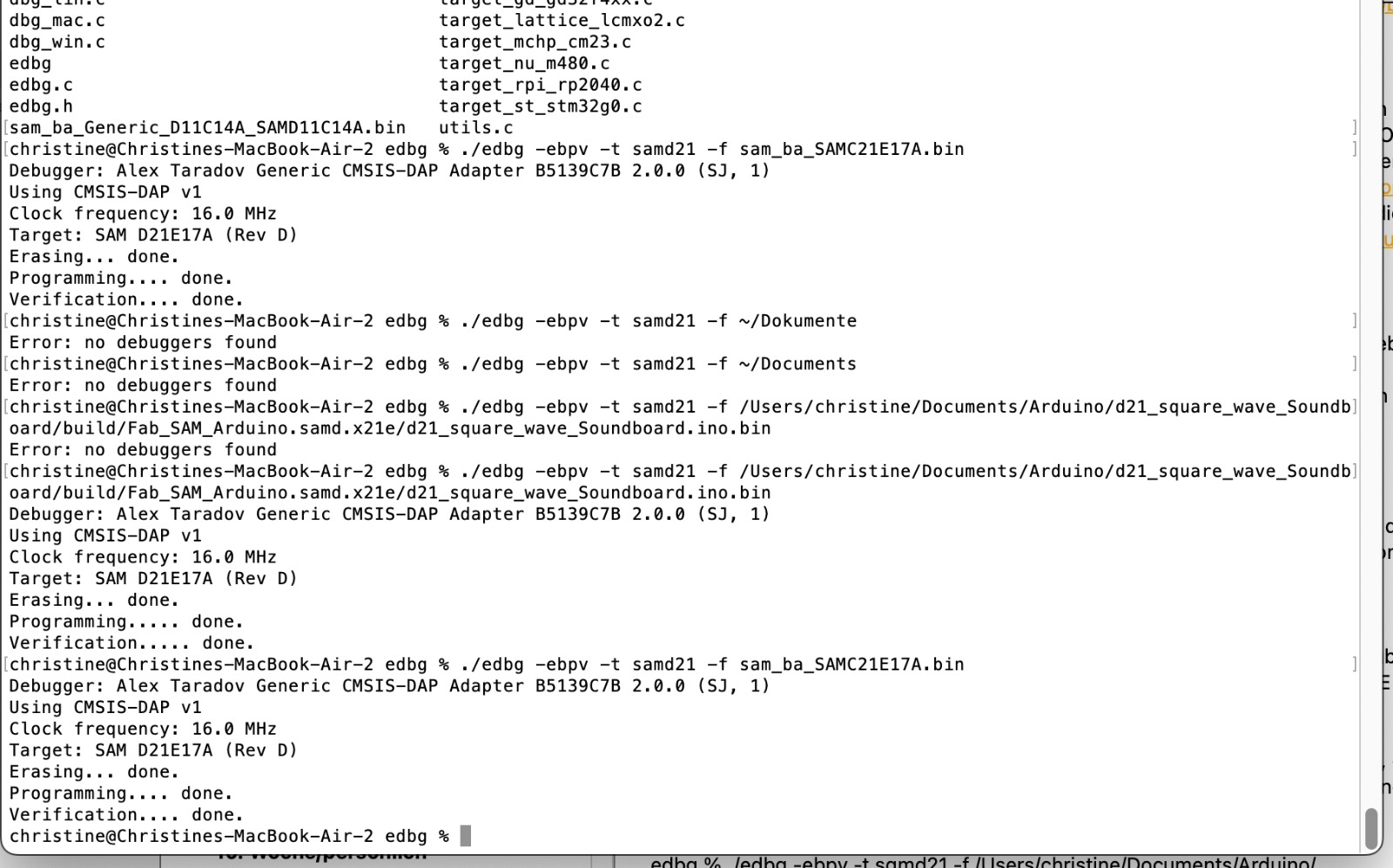
edbg % ./edbg -ebpv -t samd21 -f sam_ba_SAMC21E17A.bin (the second part of the command that followed edbg % ./ was taken from the SAMD21E Piano page).
It seemed as if everything had worked successfully because the terminal replaid done. Unfortunately, we could not then program the board because it was not recognized by the Arduino IDE. We couldn't see the reason. So, we took another step. We tried to load the Arduino IDE program onto the PCB directly without a bootloader. Wie found the program at the Piano page. We download the programm an used the following command:
edbg % ./edbg -ebpv -t samd21 -f /Users/christine/Documents/Arduino/d21_square_wave_Soundboard/build/Fab_SAM_Arduino.samd.x21e/d21_square_wave_Soundboard.ino.bin
Again, it seemed as if everything had worked successfully. But again, we could not recognize the PCB with Arduino IDE and cound not program it.
ESP32S3 - Capacitive touch
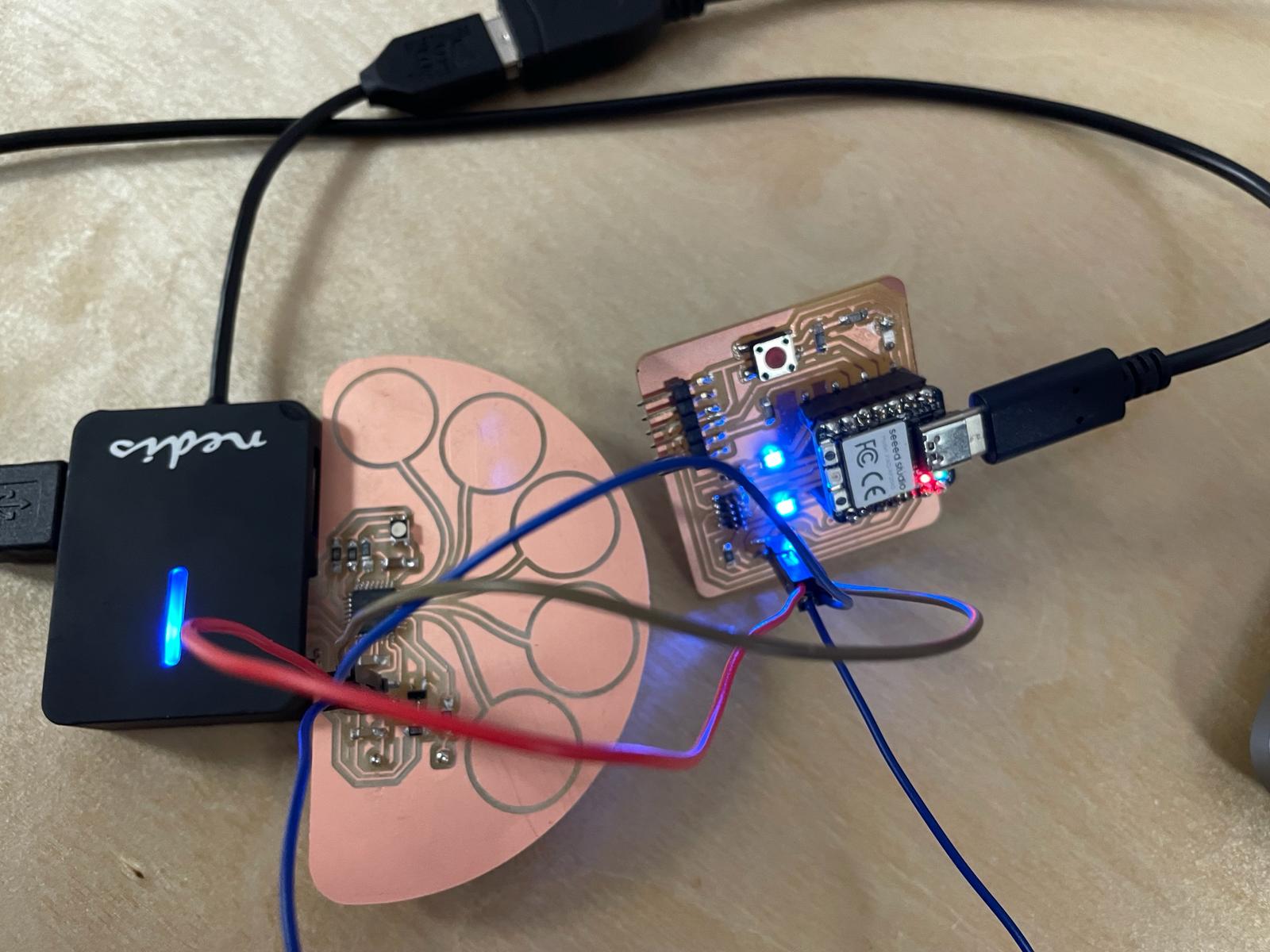
For this assignment I used the board which I had already made. I discribed the process in Week 8. I created my capacitive touchpads for the box using copper tape, to which I soldered a wire. To secure the solder joint, I applied a small piece of copper tape on the opposite side. I then connected this wire to the pins of my board. I used GPIO pins 3 through 14. For more information of the building process you can check my system integration side. For the sound, I had already tested a simple code with the Barduino. I extended this code to include all the pins I wanted to use with the ESP32S3. After connecting the board, it was crucial to work serially to read if the code worked and what changes were needed to trigger sounds at specific capacitance changes. A classmate recommended defining a threshhold to avoid changing everything when the threshold is altered, but only adjusting it once in the code. In the code, it looked like this:
The following points were important for the code:
 I established a TX RX connection to the DFPlayer.
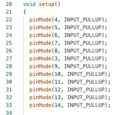 I defined PinMode 4 to 14 as input_pullup.
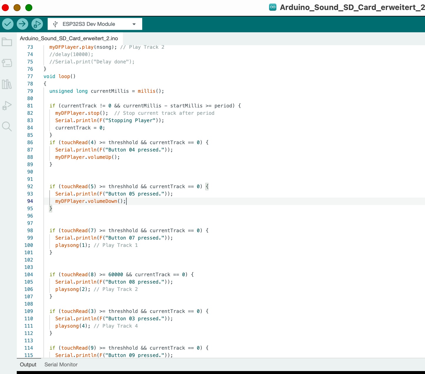
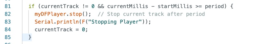 I programmed the loop so that when one of the pins is activated, a song is played.
However, with the serial print I found that not all touchpads have the same capacitive change. Therefore, I had to adjust the threshold individually in some places, e.g., for pin 8:
I was very happy, wenn I saw the Board working really well.
In the following videos, you can see that I pressed the capacitive touch pin to change the capacitance. You can see that when it's not pressed, the capacitance is around 30.000. When it's pressed, it's around 90.000.